18P — Raspsaber
Par admin le mardi, mai 15 2018, 20:00 - 2017-2018 - Lien permanent
This project is the continuation of the one of last semester. It's an attempt at building a Raspberry-pi controlled lightsaber using the rpi_ws281x library in python. The blade is composed of two addressable NeoPixel ws2812b RGB LEDs strips by Adafruit. The sabre is equipped with an ADXL345 accelerometer.
This work has been done by Héloïse PIGUET.
1. Introduction
In my first introduction, I dwelled on all the amazement making things can bring to one self. But this was before I actually tried to tackle such ambitious enterprise. The art of prop-making (1), amateur or not, can be technical and require a diverse set of skills.
However, it's on this very spot that the essence of cosplay (2) and costume-making lies. Crafting and creating things is bound to be challenging. And challenge there is. If the construction of various types of homemade sabers has been widely anchored in the Maker (3) community, mostly using Arduino (7) or other similar microcontrollers (4) (5) (6), Raspberry-controlled lightsabers are like rare exotic birds (14).
Last semester, I started working on a P.O.C of a Raspberry-driven lightsaber to go along my sith cosplay.

1. Lightsabers examples and their application to cosplay | (8) fancy blades by LToy creation on Etsy, (9) steampunk sabre by Nocturne armory and (10) Sith cosplay by Swiss Stylouz cosplay
1.1 Goal
Building a full lightsaber prop with functional blade and sturdy hilt. The sound is optional and will be upgraded depending on the time left.
1.1.1 Functionalities (optional)
- Blade opening and closing animation
- Flash animation when the blade is hit
- Humming sound when the blade is out
- Impact and acceleration sound when the sabre is manipulated
1.1.2 Milestones
- Clean up the P.O.C algorithm and retrieve useful parts
- Upgrade the colour selection menu
- Link the accelerometer code with flash effect when hit
- Set up the JustBoom DAC Zero pHat and quickly test the sound output
- Look for flash and humming sound or sound libraries
- Link the main blade algorithm and the hit code with respective flash and humming sounds
1.2 Raspberry zero
As for his big brother Raspberry Pi, the Raspberry Zero is a nano-computer consisting of a motherboard equiped with several ports such as HDMI and micro-USB. It has the same specifications than the B+ model, without the ethernet ports and can be wireless (LAN). It also has a hat-compatible 40-pin GPIO header. The main advantage is his size, with his 250 mm of width, perfect to fit the handle of the sabre.

2. Raspberry Zero overview | (17)
As you can see, the pinout of the Zero is basically the same as the one of the Raspberry B+. The decisive pins are the 18, for PWM
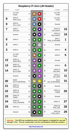
3. Raspberry Zero GPIO pinout | (18)
1.3 Libraries
By default, the Raspberry isn't able to drive LEDs since it doesn't do real time operating system. In order to have the specific timing required, I'm using a library that uses the PWM and DMA hardware to generate a signal of peculiar duty-cycle so that the LEDs strip can read the data input (More informations here (15)).
I also needed something to use the accelerometer and retrieve the data.
2. Materials and Method
2.1 Materials
- 1x Raspberry Pi B+ Zero
- 1x Medium-sized breadboard
- 15x Jumper cable (male-to-male)
- 4x Jumper cable (male-to-female)
- 2x 60~LEDs/m addressable RGB WS2812B NeoPixel LEDs strip (11)
- 2x 10k Ohm resistor
- 1x Micro-USB cable
- 1x GPIO-compatible ribbon cable
- 1x USB-Ethernet dongle adapter
- 1x COM-00097 push button
- 1x SPST ON/OFF Switch
- 1x Sparkfun pi Wedge B+
- (1x JustBoom DAC Zero pHat (12))
- 1x ADXL345 accelerometer (13)
- 1x 10000mAh Mi Power Bank (19)
2.2 Method
2.2.1 Wiring
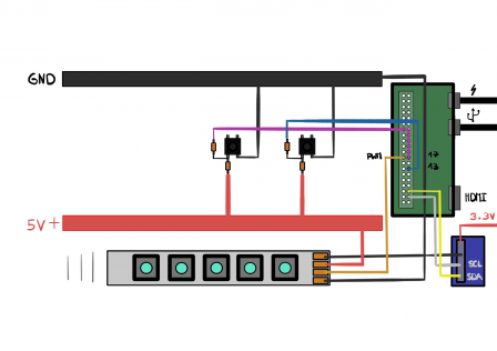
4. Overall wiring diragram
The Raspberry Zero is connected to a standard DC wall power supply. Though Wifi can be enabled, for the sake of simplicity, the Zero is connected to the LAN with the data USB port using an Ethernet dongle adapter. To program it, SSH connection is employed via command line.
Input
- Push button (pin 17)
- Push button (pin 13)
- ADXL345 (SDA and SCL) using smbus, I2C protocol (More info (15))
Output
- Neopixel RGB LEDs strips (pin 18) wired in parallel with the Zero
2.2.1.1 Blade
The blade consists of two LEDs strip sticked together. In order to be driven, they need to be wired together in the right data direction.
- GND on GND
- DIN on DIN
- +5V on +5V
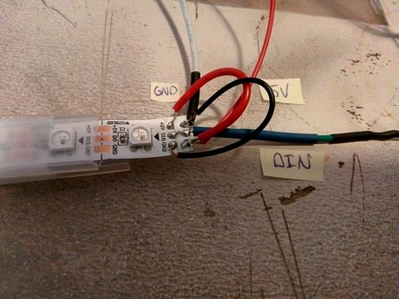
4. Wiring of the LEDs strip
Since the wires are really short, it can be tricky to solder them properly. Bending them might reduce the stress on the connection points and makes it easier for a newbie. Here I took good care to cross the GND and 5V wires, because the strips are attached together.
After the whole development, the strip will be slipped in a polycarbonate tube, inside some diffusing material and act as a blade.
2.2.1.2 Battery
The Zero requires a 5V and 2.5A power input, easily achieved via the 5V USB port. The ws281x addressable pixels can draw up to 60mA at full white. Considering the two meters of strip with a density of 60 LEDS/m I own, so a bit under 120 individual LEDs, a good DC 5V 2A is going to be enough since the LEDs will rarely be white all the time. I managed to obtain a LI-ION battery with those exact specs, but unfortunately, the thing is a smart USB-compatible rechargeable battery. And the USB part meant that I had to find a way to connect the jumper wires from the strips to a female USB port.
In the true spirit of hacking and due to my lack of time and money, I stripped an old USB cable, and soldered the +5V and GND wires to old male-to-male jumper.
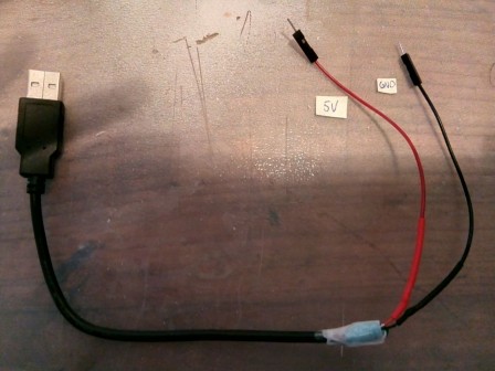
5. Rough USB-jumper adapter
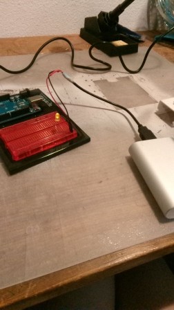
6. USB-jumper adapter fruitful test

7. MI LI-ION battery overview
Obviously, the battery won't fit the handle, but it came handy for the testing and programming. The various upgrades that can be done will be explained in the part 4.
2.2.1.3 Accelerometer

8. ADXL345 basic wiring
Nothing too fancy, wire the pin alike together. Female-to-male jumper were used to allow free movement.
- GND on GND
- 3.3V on 3.3V
- SDA on SDA
- SCL on SCL
2.2.2 Code
2.2.2.1 Basic functions
The library comes with a low and high API, the high one was used, since only the basic methods were needed.
numPixels()Returns the number of pixels in the display, useful when using loops to animate said pixels.show()Updates the hardware, the only function that actually sets the LED color.Color(red, green, blue)Convert the provided red, green, blue color to a 24-bit color value. Each color component should be a value 0-255 where 0 is the lowest intensity and 255 is the highest intensity.begin(self)Initialize library, must be called once before other functions are called.
Moreover, a "strip" class needs to be created so that the methods can apply to it (16).
init(self, num, pin, freq_hz=800000, dma=5, invert=False)
Num should be the number of pixels in the display, and pin should be the GPIO pin connected to the display signal line (must be a PWM pin like 18!). Optional parameters are freq, the frequency of the display signal in hertz (default 800khz), dma, the DMA channel to use (default 5), and invert, a boolean specifying if the signal line should be inverted (default False).
2.2.2.2 Structure of the algorithm
The script that drives the LEDs is basically a big loop while True:, triggered by the button, in which several functions are called to open, close or change the color of the blade.
To avoid switch bounce (20), or the multiple enabling of a button due to its structure, the push-button has been wired in pull-down. Instead of setting the pulse at HIGH when triggered, and risking blurry enabling, the pulse is HIGH by default, and the push sets it in LOW. The input is read by the Zero through input = GPIO.input(13), and needs to be defined beforehand this way GPIO.setup(13,GPIO.IN). The pull-down is handled by adding a boolean operator on the input value if (not input}:.
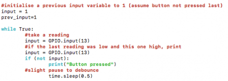
- 1. Opening function

Here, a loop enables each pixel of the strip gradually for i in range(strip.numPixels()):, numPixels() retrieves the number of LEDs on the strip and the function range() generates a kind of list that can be useful to iterate an action without caring for the index.
strip.setPixelColor(i, color), pretty self-explanatory, allows to set the pixel colour using Color() when the function is called. Finally, strip.show() actually enables the change of state of the LED.
- 2. Colour changing function

The only difference with the previous function is that there is no need of delay, since all LEDs are set at the same time. Moreover, strip.show isn't implemented in the loop. This is relevant, since python's structure is based on tabulation.
- 3. Flash function

When the ADXL345 returns sufficient acceleration - we'll see this point a bit later - the flash or impact function is engaged. The variable iteration defines how many times the main loop will be done. There are three loops nested inside one another. The first determines the range of iteration, the second defines a smaller range of two LEDs together and the two last establish the actual blinking of the pixels.

i+q considers both levels of loop, so that every two pixels, one is disabled.
- 4. Closing function

Since the range() function is quite limited, and since strip.numPixels() needed to be the maxima of the loop, while: was used to shut down each LEDs from the last of the strip. The i variable is attributed to the highest number of LEDs and incremented bakward via i = i-1.
In order to make the sabre react to movement, I employed the ADXL345, which is a three-axis accelerometer and allows to retrieve acceleration data from all axes in g (earth gravitation).

Using the ADXL345 library shown earlier, once the accelerometer object defined accel = adxl345.ADXL345(), the axes values are harvested with accel.getAxes(True). A simple test tells whether or not one of the measured accelerations is above a set value in level. The threshold value has been defined trough rough experimentation of the sensibility of the accelerometer, since no precise measurement is required. The flash function is triggered when the test of acceleration returns True.
3. Results
9. Algorithm show off
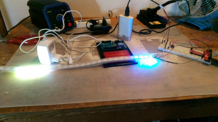
10. Unworking LEDs strip
Booted the exact same way, the double strip didn't responded as planned. The enabling of the LEDs lagged and didn't follow any logic. Since the whole algorithm worked with the prototype, the issue couldn't come from the software part. I'll explain afterward what might have happened.
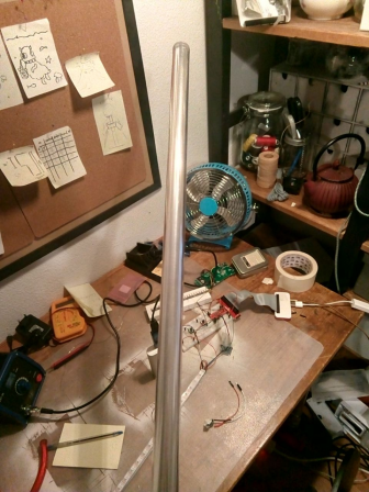
11. Polycarbonate blade and tip with diffuser
The strips were supposed to slide into this 2 mm x 250 mm width meter of strong polycarbonate tube, courtesy of a friend of mine. The inside is covered with plastic diffuser and the tip has a reflective aluminium side.
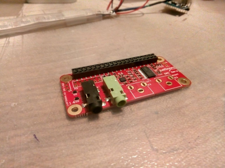
12. Unused Phat with jack output
Due to my lack of time and several technical difficulties, the sound part of the sabre hasn't been covered. This might be the object of further development.
4. Discussion
This project is the continuation of what has been prototyped and tested last semester. Since then, a few milestones have been reached. Although I faced a lot of technical difficulties, I still managed to obtain a few upgrades of my last project.
4.1 Positive aspects
Globally speaking, most of the software aspects have been covered, and though the main strip didn't work, the algorithm reached a satisfactory level. A selection button has been added and a colour menu was made as planned. The main functions have been implemented, and the accelerometer input works well. My knowledge of Python has greatly improved from knowing peanuts to being actually able to modify an example script to my needs. I'm far away from being good at it, but from an engineering point of view, my code does the job.
4.2 What went wrong
First I had to change platform, since I wanted to go closer to a working lightsaber using RPI technology. What I though to be a formality happened to be a void in which I lost four days of work. I had a really hard time setting up the Zero, mostly because it has fewer ports and a hardly-working GUI. I couldn't connect easily via SSH because the WIFI wasn't enabled. Moreover, I couldn't use the first SD card, because for some reason the sudo command didn't work. I couldn't run basic scripts and this meant that I wasn't allowed to have the lower access required by my libraries. Even though I asked everywhere and went to more experienced users to seek help, nobody understood the issue. After a long and frustrating struggle, I flashed a new SD card and started from the bottom again, re-installing every library and dependencies. Then, I had to retrieve my scripts from the git, but this was also a pain, since it was a mess. When I finally recovered everything, I had nearly lost a week. I no longer had the time to develop a sound output part.
Although the coding part went pretty much without bugs, when I attempted to try my newly soldered LEDs strip, the LEDs weren't working properly. After I isolated the problem to a hardware issue, I realised - too late - that in order to read the data, the WS2812x LEDs needed a signal of 5V, and yet the PWM pin has an output of only 3.3V. I needed a level shifter of this type (21). I had no time and attempted a few desperate solutions using a small voltage modulation chip (22), because apparently, it was possible to alter the tension of the powering signal, so that the ratio between the PWM output and the power could be under 0.7 and so allow the data to be read. It didn't work.
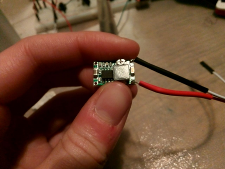
13. Mini-360 DC-DC Buck converter
For the sound part, as I said, from the beginning I sort of knew I wouldn't have the time. More than that, I recently found out that with the specific kind of WS281x I own, it is impossible to have both a sound output and drive LEDs, since both require PWM (23) and because the Raspberry operating system doesn't do real-time like Arduino for instance. I shall find another use for the Phat I bought.
5. Conclusion
To conclude, it has been an interesting and challenging project, far away from my comfort zone and probably way too ambitious for my current skillset (or the lack there of). Although I still obtained a few results, I am in no way satisfied with my actual "lightsaber".
Moreover, using a Raspberry Pi to drive LEDs strip and create a working, fully animated lightsaber isn't a clever nor efficient way to do it. The technology isn't made for such use, and the most basic action done with a micro-controller turns out to be really tricky with a Raspberry. Sure, it's possible to drive a lot of strips with the library I used, but the overall structure of python doesn't suit the construction of an easy sabre. The difficulties I faced came mainly from the lack of documentation on the subject. The only project I found (14) has been made by a german duo of student for their Bachelor in engineering. I contacted them, but they weren't open to share their experimentations.
However, I will still try to build a lightsaber myself, but this time using Arduino or Teensy instead.
6. Glossary
- API Application Programming Interface is a set of functions and procedures that allow the creation of applications which access the features or data of an operating system, application, or other service.
- PWM Pulse-width modulation is a modulation process or technique used in most communication systems for encoding the amplitude of a signal right into a pulse width or duration of another signal, usually for transmission.
- DMA Direct Memory Access (DMA) is a capability provided by some computer bus architectures that allows data to be sent directly from an attached device (such as a disk drive) to the memory on the computer's motherboard. Basically it by-passes the CPU.
- duty-cycle is defined as the ratio between the pulse duration, or pulse width and the period of a rectangular waveform. It is the fraction of one period in which a signal or system is active.
References
- (1) https://en.wikipedia.org/wiki/Prop_replica
- (2) https://www.merriam-webster.com/dictionary/cosplay
- (3) https://www.wired.co.uk/article/maker-movement
- (4) http://fredrik.hubbe.net/lightsaber/
- (5) https://www.iliketomakestuff.com/make-lightsaber/
- (6) https://saberforge.com/
- (7) https://www.arduino.cc/en/Guide/Introduction
- (11) https://www.adafruit.com/product/1138
- (12) https://www.justboom.co/product/justboom-dac-zero-phat/
- (13) https://www.adafruit.com/product/1231
- (15) https://oci.gyre.ch/blog/?post/2018/02/02/18H-piguet
- (16) https://jeffknupp.com/blog/2014/06/18/improve-your-python-python-classes-and-object-oriented-programming/
- (19) http://www.mi.com/en/pb10000pro/#params
- (20) https://www.allaboutcircuits.com/technical-articles/switch-bounce-how-to-deal-with-it/
- (21) https://www.digitec.ch/en/s1/product/ti-74ahc125-quad-level-shifter-3v5v-electronics-supplies-casing-5999557?dclid=CMnbprO9gtsCFQGTdwodOVIDQw&gclsrc=aw.ds&gclid=Cj0KCQjwxN_XBRCFARIsAIufy1bIWdfSUIVl6Lqb3eiIlIU71IfcTmpH27bb8ENTvc4emVwlZCv-SdQaAh9SEALw_wcB
- (22) https://solarbotics.com/product/40410/
- (23) https://tutorials-raspberrypi.com/connect-control-raspberry-pi-ws2812-rgb-led-strips/
Media
- (8) https://www.etsy.com/listing/564216513/star-wars-rebels-dark-saber-blade?ga_order=most_relevant&ga_search_type=all&ga_view_type=gallery&ga_search_query=star+wars&ref=sr_gallery-1-39
- (9) http://www.nocturnearmory.com/steampunksabers.html
- (10)https://www.facebook.com/StylouzCosplay/photos/a.2040896619260059.1073741866.420176671332070/2063649880318066/?type=3&theater
- (14) https://www.youtube.com/watch?v=O6XuSB7ozVk
- (17) https://uk.pi-supply.com/products/raspberry-pi-zero-cable-kit
- (18) http://pi4j.com/pins/model-zero-rev1.html